How to show current location on Google Map in Icenium

In this post we will take a look on working with Google map in Icenium. We will display Google map pinned with current location in a mobile view.

image

On creating Cross-Platform mobile application (Kendo UI Mobile) in Icenium, you will find by default references to work with Google map added in the project.

clip_image002

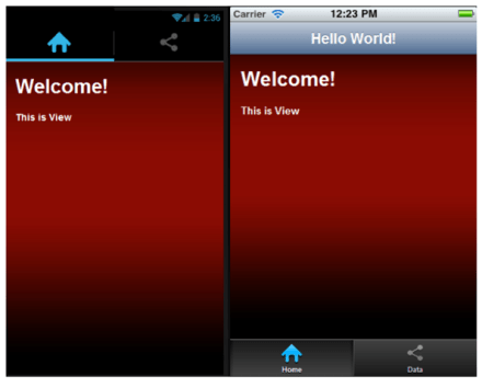
Next we need to create a view. In this view map will be rendered,


<div data-role="view" id="map" data-title="Map" data-show="showMap" data-stretch="true">
<div>
<div id="map_canvas" style="width: 100%; height: 100%; position: absolute;">
</div>

</div>
</div>

There are certain points worth discussing about the view.

  • showMap function will be called whenever user is navigating to view.
  • Style of map-canvas div is set to 100% width and height such that map will be displayed in whole view.

Now we need to write showMap function. In this function we will call PhoneGap navigatior.geolocation.getCurrentPosition function to get the longitude and latitude of current location of the user.


function showMap() {

navigator.geolocation.getCurrentPosition(
onSuccessShowMap,
onErrorShowMap
);

}

navigatior.geolocation.getCurrentPosition will call onSuccessShowMap function on success and onErrorShowMap on any exception in finding users current location. In onSuccessShowMap function we will render Google map in the view created previously.

Rendering of Google map can be done in three steps,

Very first we need to find longitude and latitude of the current location and that can be done as following,

image

Once longitude and latitude has been determined next we want to create the map option. You can read more about Google map options in Google map API documentation. So we are creating map option as following,

image

After creating map option we need to create the map. It takes two parameters. First HTML element on which you want to render the map and then map options. We have created a div with id map-canvas in map mobile view to render the map and in previous step, we created the map option.

image

At the last step we need to set the marker on the map with the current location. That can be done as following,

image

To render map you need to consolidate all the steps discussed above in onSuccessShowMap(position) function. After consolidating function should look like below,


function onSuccessShowMap(position) {

var latlng = new google.maps.LatLng(
position.coords.latitude,
position.coords.longitude);

var mapOptions = {

sensor: true,
center: latlng,
panControl: false,
zoomControl: true,
zoom: 16,
mapTypeId: google.maps.MapTypeId.ROADMAP,
streetViewControl: false,
mapTypeControl: true,

};

var map = new google.maps.Map(
document.getElementById('map_canvas'),
mapOptions
);

var marker = new google.maps.Marker({
position: latlng,
map: map
});
console.log(marker);
console.log("map rendering");
}
</script>

In last we need to write onErrorShowMap function. In this function handle all the errors may encounter while reading current location of the user. I am leaving function like following


function onErrorShowMap(error) {

alert("error");
}

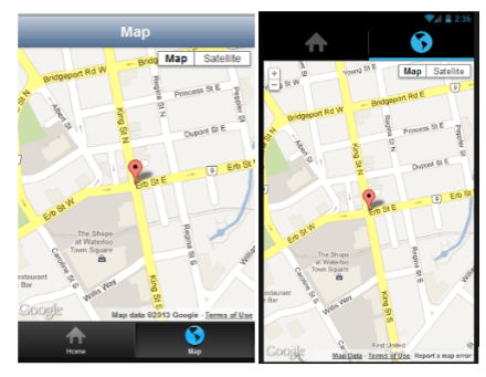
Now when you run application you should get map with user current location in the map view.

image

I hope you find this post useful. Thank for reading.

Few Queries on Test Studio : Answered

Recently I was giving demo on Test Studio. While demo there were few questions popped up . In this blog I am consolidating those questions such that it would be useful for all Test Studio users.

image

Does it work with Telerik SL CONTROLS

Yes Test Studio support SL controls. For demo, please see Telerik TV and look at the videos listed under the Silverlight tag:

http://tv.telerik.com/products/automated-testing-tools?FilterByTags=Silverlight

How would it integrate into a CI ENVIRONMENT

You can find more details about CI integration at

http://www.telerik.com/automated-testing-tools/support/documentation/user-guide/command-line-test-execution.aspx

How Test Studio works with MS LAB

We don’t have anything specific with how we integrate with the TFS/VS lab environment.

How does it run tests? Does it require agents to installed

If you want the tests run via the scheduler or remotely then you do need an agent installed. You can find more details here

http://www.telerik.com/automated-testing-tools/support/documentation/user-guide/scheduling-test-runs.aspx

Does it support SL 4 +

Yes Test Studio supports Silverlight 4+

Does it support mobile platforms like Windows Phone, Android and iPhone

Test Studio supports IOS but as a separate product. Currently Test Studio do not support Windows Phone and Android

Can Test Studio Framework API can be used from MS TEST

Yes it can be used with MS Test.  You can find more details at

http://www.telerik.com/automated-testing-tools/support/documentation/user-guide/command-line-test-execution/mstest.aspx

http://www.telerik.com/automated-testing-tools/support/documentation/user-guide/write-tests-in-code/intermediate-topics/settings-and-configuration/settings-class.aspx

I hope you find this post useful. Thanks for reading.

Three steps of working with JavaScript Array and Kendo UI Mobile ListView

In this post we will learn working with JavaScript array and KendoUI Mobile ListView in three simple steps.

Step 1: Create Data Source

Very first you need to create data source. Application can read data from various sources. Some of the source can be as following

  • Reading data from remote data source
  • Reading data from local memory
  • Reading static data from local array.

Let us create a data source by reading data from local array.


var speakers = [
{

SpeakerName: "Chris Sells",
SpeakerTitle: "Author, Ex- Microsoft and ardent community contributor",
SpeakerPhoto: "speakerimages/cs.jpg"

},
{

SpeakerName: "Steve Smith",
SpeakerTitle: "Speaker, Author, Microsoft Regional Director and MVP",
SpeakerPhoto: "speakerimages/ss.JPG"

},
{

SpeakerName: "Dr.Michelle Smith",
SpeakerTitle: "Enterprise Consultant",
SpeakerPhoto: "speakerimages/ms.jpg"

},
{

SpeakerName: "Gaurav Mantri",
SpeakerTitle: "Founder Cerebrata & Windows Azure MVP",
SpeakerPhoto: "speakerimages/gm.JPG"

}

];

Step 2: Create Template

Template is the way to tell the platform the way you want to display data. You already have data and next you need to decide the way you want to display or render data. In Kendo UI Mobile you can create template as following,


<script type= "text/x-kendo-template" id="speakersTemplate">
<div>
<img src=#=SpeakerPhoto# alt="#= SpeakerName #" />
#= SpeakerName #</br>
<span>
#=SpeakerTitle#
</span>
</div>
</script>

To create Kendo Template, You need to create a script with type text/x-kendo-template. Values from data source will be rendered by putting property name as following

image

In above case source of an image can be set as following. SpeakerPhoto and SpeakerName are properties of data array.

image

To make data rendering more immersive you need to set the style of data in CSS. You will notice in above template that we are setting class attribute of img and span tag. These classes are defines in CSS as following,


.pullImage {
width: 64px;
height: 64px;
border-radius: 3px;
float: left;
margin-right: 10px;
}

.listTime
{
font-size: .8em;
font-weight: 100;
}

Step 3: Create ListView

By step 2 you have created data source and template. Next you need to create ListView. Creating ListView is very simple and can be created as following,


<div data-role="view" id="dataview" data-title="Data">

<div>
<ul id="speakerslist"
data-template="speakersTemplate"
data-source="speakers"
data-endlessScroll="true"
data-role="listview"
data-style="inset">
</ul>
</div>

</div>

To create ListView you need to set data-role attribute of <ul> element as listview. To define how data should be displayed in the ListView set data-template attribute and data source can defined by setting data-source attribute.

Note: if we have put speaker’s photos locally in spakerimages folder. Since we are setting speaker photo attribute in Speaker JavaScript array.

Running the Application

On running of the application you should get ListView with speaker’s details as following

image

In this way you can work with data from JavaScript array and Kendo UI mobile ListView. I hope you find this post useful. Thanks for reading.

Telerik India wishes you happy New Year 2013

Telerik India wishes you very happy New Year 2013. We hope you will have healthy , happy and successful year ahead.

image

We are determined to help you in “Delivering more than Expected “. You will find us around all the community events and conferences in India.

We will create more blog posts and deliver 2 webinars each month in India time zone to expedite your learning and knowledge on various Telerik Products.

Once again we wish you joyful New Year. Let us work together in this year to “Deliver More Than Expected

How to work with Pie Charts in JavaScript based Application for Windows 8

In this post we will take a look on working with Pie Charts in JavaScript based Application for Windows Store. We will follow step by step approach in this blog post.

Step 1: Add References

Very first we will add Telerik JS and CSS files references in the project. If first time you are working with Rad Controls in Windows 8, I suggest you to read blog post to setup the environment

After adding the files in the project we need to refer them on the html file . Files can be referred as given in following code snippet.

<!--Telerik References -->
 <script src="/Telerik.UI/js/jquery.js"></script>
 <script src="/Telerik.UI/js/ui.js"></script>
 <link href="/Telerik.UI/css/dark.css" rel="stylesheet" />
 <link href="/Telerik.UI/css/common.css" rel="stylesheet" />

Step 2: Create a Chart

A Pie chart can be created by setting data-win-control attribute of a div as Telerik.UI.RadChart and setting series type as pie


<div id="performancechart" data-win-control="Telerik.UI.RadChart"
 data-win-options="{
 series: [{
 type: 'pie',
 data : [

{value:30,category:'Math'},
 {value:20,category:'Physics'},
 {value:22,category:'Chemistry'},
 {value:28,category:'Economics'}

 ],
 lables :
 {
 visible:true
 }

 }
 ]}"

 />

&nbsp;

In above code snippet,

  • We are setting data-win-control attribute as Telerik.UI.RadChart
  • In data-win-options , series type is set as pie
  • In data-win-options data is set locally.
  • Data array contains two properties. They are values and categories

At this point if we go ahead and run the application, we will get an output something like below

image

Step 3: Configure More Pie Chart options

You can configure common options of char series as discussed in this blog post . Apart from common options you can configure options like following,

  1. colorField
  2. explodeField
  3. categoryFiled

Assume you have data source as following

image

You can configure these values for pie chart as following

image

On running you will pie chart as following. You will find that colours of categories have been changed.

image

You can explode a category as following. Even though in following example we are setting explode attribute with explode property in data array, you are free to set any property of data array as explode field by setting explodeField attribute as we set colorField.

image

On running you will pie chart as following.

image

In this we can work with pie charts. Below is the consolidated code of above discussion


<!DOCTYPE html>
<html>
<head>
 <meta charset="utf-8" />
 <title>TestDemoJavaScript</title>

<!-- WinJS references -->
 <link href="//Microsoft.WinJS.1.0/css/ui-dark.css" rel="stylesheet" />
 <script src="//Microsoft.WinJS.1.0/js/base.js"></script>
 <script src="//Microsoft.WinJS.1.0/js/ui.js"></script>

<!--Telerik References -->
 <script src="/Telerik.UI/js/jquery.js"></script>
 <script src="/Telerik.UI/js/ui.js"></script>
 <link href="/Telerik.UI/css/dark.css" rel="stylesheet" />
 <link href="/Telerik.UI/css/common.css" rel="stylesheet" />

 <!-- TestDemoJavaScript references -->
 <link href="/css/default.css" rel="stylesheet" />
 <script src="/js/default.js"></script>
</head>
<body>

 <h1>Chart Demo</h1>

<div id="performancechart" data-win-control="Telerik.UI.RadChart"
 data-win-options="{
 series: [{
 type: 'pie',
 data : [

{value:30,subject:'Math',color :'red',exlode : 'true'},
 {value:20,subject:'Physics',color:'blue',explode:'false'},
 {value:22,subject:'Chemistry',color:'green',explode:'true'},
 {value:28,subject:'Economics',color:'gray',explode:'true'}

 ],
 field: 'value',
 categoryField: 'subject',
 colorField :'color',
 lables :
 {
 visible:true
 },
 tooltip :
 {
 visible : true
 }

 }
 ]}"

 />

&nbsp;

</body>
</html>

&nbsp;

Future Post

In this post we learnt working with pie Charts. We focused on only one type of series. In further posts we will explore various series type and working with remote data in the Rad Chart. I hope you find this post useful. Thanks for reading.

How to set background image of Kendo UI Mobile View

In this post we will take a look on how to set background image of Kendo UI Mobile view. Let us say we have a view as following,

image

This Kendo UI Mobile View is created as following,


<div data-role="view" id="tabstrip-home" data-title="Hello World!">
<h1>Welcome!</h1>
<p>
This is View
</p>
</div>

Now you have a requirement to put a background image in this view and set the colors of the texts on the view. You can do it by setting style of div in the CSS. This can be done as following


#tabstrip-home .km-content{

background-image: url('../appimages/backgroundimage.jpg');
background-size: auto 100%;
background-repeat: repeat;
color : white;

}

In above code snippet ,

  1. Tabstrip-home is id of the view. Background image of this particular view will be set to an image.
  2. Background image is inside the folder appimages. We are setting backgroundimage.jpg as the background of the view.
  3. Image will repeat itself as background of the view.
  4. Text of the view content has been set to white.

After setting style view should look like as following image,

image

In this way you can set an image as background of KendoUI Mobile View. I hope you find this post useful. Thanks for reading.

Create APK package for Google Play using Icenium Graphite

In this post we will take a look on creating APK package for submission to Google Play using Icenium. Let us follow following walkthrough to create APK package,

To create package, Right click on the project and select Publish to create APK package,

clip_image001

In the next window click on Google Play. You will get an error message that there is no certificate or Code Sign Identity found for Google Play Signing.

image

To solve this issue click on the option in Icenium Graphite IDE.

image

In Users Option window select General tab and then Certificate Management option.

image

In Certificate Management option you will get an option to create New Certificate. Click on Create New to create new certificate. You can either use

  1. Self-signed identity
  2. Request for the Certificate

Let us go ahead and request for the Self-signed identity. In Self-signed identity window you need to provide following vital information,

  • Country
  • Type of the self-signed identity. In this choose Google Play as option. Other option available is Generic.
  • Configure Start Date and End Date

image

After creating Self-signed identity you can find them in Cryptographic Identities section. Below you can see that I have created three self-signed identity.

image

After creating Self-signed identity right click on the project and select properties in the properties windows, select Android tab. Here you can set various application properties for android platform.

image

From the Code Signing Identity drop down, select any existing certificate to associate it with the application.

image

You can set icons, application permissions for Google Play here. After associating self-signed identity again right click on the project and select publish option. You will get Application Validation Status message as OK.

image

Next click on the Build button to create the package. Icenuim will build the application in cloud and ask you to give a name of the apk package and save it locally.

image

In this case we saved APK with name tearchapp. Now you can submit the APK file to Google Play to publish application. I hope you find this post useful. Thanks for reading.

Make a Call on Icenium using PhoneGap

In this post we will take a look on making a call using PhoneGap in a Hybrid application creating using Icenium. Let us create a view like following to make a call,

image

Above view can be created using following code snippet,


<div data-role="view" id="callview" data-title="Make a Call">
<h1>Call this number!</h1>
<div id='Div1'>
<label for="txtName" style="display: inline-block;">Enter Phone Number to Call:</label>
<input type="text" id="Text1" value="" />
</div>
<div>
<a id="A1" data-role="button" data-click="callfunction" data-icon="action">Make A Call</a>
</div>
</div>

On click of Make a Call button a call can be done as following,


function callfunction() {

var phntocall = document.getElementById('txtPhoneNumber1').value;
window.location.href = "tel:" + phntocall;

}

In above code snippet we are reading phone number. After that using tel: to make a call. It will open native Call application with configured phone number to make a call.

I hope you find this post useful. Thanks for reading.

How to fetch data of selected item in KendoUI Mobile ListView

In this post we will take a look on how to read data value of selected item in KendoUI Mobile ListView. Let us say you have a ListView as given in following image,

image

As you see that there is button in each ListView item and on click of the button you need to fetch the selected phone number to make a call.

Above ListView can be created as following,


<div data-role="view" id="policestationview">

<ul data-role="listview"
id="policestationlistview"
data-style="inset"
selectable="true"
data-source="somedata"
data-template="sometemplate"
data-click="somefunction">
</ul>

</div>

In above view

  • Data source is set to somedata
  • Data Template is set to sometemplate
  • Most importantly data-click is set to a JavaScript function

Now in function you can fetch selected item on click event of ListView as following,

image

In above code snippet phonenumber and name is properties of the array set as the data source of the listview. For your reference datasource is as following. You can see that name and phonenumber are properties of the array used to create datasource.


var dataarray = [

{ name: "Darya Ganj", phonenumber: " 01123274683", group: "CENTRAL" },
{ name: "Kamla Mkt", phonenumber: "01123233743", group: "CENTRAL" },
{ name: "I.P. Estate", phonenumber: "01123318474", group: "WEST" }

];

var somedatasource = new kendo.data.DataSource.create(
{
data: dataarray,
group: "group"
});

</script>

In this way you can fetch data of slecetd itm of KendoUI Mobile ListView. I hope you find this post useful. Thanks for reading.

How to work with RadChart in JavaScript based Application for Windows 8

In this post we will take a look on working with RadChart in JavaScript based Application for Windows Store. We will follow step by step approach in this blog post.

Step 1: Add References

Very first we will add Telerik JS and CSS files references in the project. If first time you are working with Rad Controls in Windows 8, I suggest you to read blog post to setup the environment

After adding the files in the project we need to refer them on the html file . Files can be referred as given in following code snippet.


<!--Telerik References -->
 <script src="/Telerik.UI/js/jquery.js"></script>
 <script src="/Telerik.UI/js/ui.js"></script>
 <link href="/Telerik.UI/css/dark.css" rel="stylesheet" />
 <link href="/Telerik.UI/css/common.css" rel="stylesheet" />

Step 2: Create a Chart

A chart can be created by setting data-win-control attribute of a div as Telerik.UI.RadChart.

image

At this point if we go ahead and run the application, we will get an output something like below

image

Step 3: Add Series

We can add series to a chart in two ways

  1. Declaratively in HTML
  2. Programmatically in JavaScript

Declaratively a series can be added by setting value of data-win-options. In following code snippet we are creating one series in the chart.


<div id="performancechart" data-win-control="Telerik.UI.RadChart"
 data-win-options="{
 series: [
 { type: 'column', name: 'Runs', data: [1000, 860,425,956,320]}

]
 }"
 />

&nbsp;

Series takes three parameters

  1. Type of the series
  2. Name of the series
  3. Data to be displayed in the series

In above code snippet, we are creating column type of series with name Runs and 5 data points. At this point if we go ahead and run the application, we should get a chart as following.

image

Programmatically chart series can be created as following,


var performancechart = document.getElementById("performancechart").winControl;
 var wicketcolumnseries = new Telerik.UI.Chart.ColumnSeries();
 wicketcolumnseries.data = [30,100,67,123,49];
 wicketcolumnseries.name = "Wicket";
 wicketcolumnseries.color = "green";
 wicketcolumnseries.visibleInLegend = true;
 performancechart.series.push(wicketcolumnseries);
 performancechart.refresh();

&nbsp;

In above code snippet following tasks has been performed

  1. Line 1: Getting reference of Chart as win control
  2. Line 2: Creating series of type Column
  3. Line 3: Setting data for the column series
  4. Line 4: Setting name of the column series
  5. Line 5: Setting colour of series
  6. Line 6: Making sure series is visible in Chart Legend
  7. Line 7: Pushing created column series to the series collection of chart
  8. Line 8: Refreshing the chart

Let us add one more series to chart declaratively in HTML.


<h1>Chart Demo</h1>
 <div id="performancechart" data-win-control="Telerik.UI.RadChart"
 data-win-options="{
 series: [
 { type: 'column', name: 'Match', data: [30, 25,22,28,25]},
 { type: 'column', name: 'Runs', data: [500, 360,125,456,320]}

],

 }"
 />

&nbsp;

So far we have added three series to chart. At this point of we go ahead and run the application then we should get a chart as following

image

There are many other types of series. We will explore them one by one in further posts.

Step 4: Add Category Axis

Category Axis can also be added in two ways,

  1. Declaratively in HTML
  2. Programmatically in JavaScript

In HTML we can add Category Axis as following


<div id="performancechart" data-win-control="Telerik.UI.RadChart"
 data-win-options="{
 series: [
 { type: 'column', name: 'Match', data: [30, 25,22,28,25]},
 { type: 'column', name: 'Runs', data: [500, 360,125,456,320]}

],
 categoryAxis: {
 categories: [2008, 2009, 2010, 2011, 2012]
 }

 }"
 />

&nbsp;

In JavaScript we can add Category Axis as following code snippet,

image

On running we will find chart with Category Axis as following,

image

Step 5: Working with Tooltip

We can configure tooltip at two levels

  1. At the chart level
  2. At the series level

Chart level tooltip can be configured as following snippet,

<div id="performancechart" data-win-control="Telerik.UI.RadChart"
 data-win-options="{
 series: [
 { type: 'column', name: 'Match', data: [30, 25,22,28,25]},
 { type: 'column', name: 'Runs', data: [500, 360,125,456,320]}

],
 categoryAxis: {
 categories: [2008, 2009, 2010, 2011, 2012]
 },
 tooltip: {
 visible: true
 }

 }",

 />

&nbsp;

At the series level we can configure tooltip as following

image

Now on running of the application we will find that when we move mouse on the chart values of the series are displayed as tooltip.

Final chart should look like as following,

image

For your reference full source code is given below,


<!DOCTYPE html>
<html>
<head>
 <meta charset="utf-8" />
 <title>TestDemoJavaScript</title>

<!-- WinJS references -->
 <link href="//Microsoft.WinJS.1.0/css/ui-dark.css" rel="stylesheet" />
 <script src="//Microsoft.WinJS.1.0/js/base.js"></script>
 <script src="//Microsoft.WinJS.1.0/js/ui.js"></script>

<!--Telerik References -->
 <script src="/Telerik.UI/js/jquery.js"></script>
 <script src="/Telerik.UI/js/ui.js"></script>
 <link href="/Telerik.UI/css/dark.css" rel="stylesheet" />
 <link href="/Telerik.UI/css/common.css" rel="stylesheet" />

 <!-- TestDemoJavaScript references -->
 <link href="/css/default.css" rel="stylesheet" />
 <script src="/js/default.js"></script>
</head>
<body>

 <h1>Chart Demo</h1>
 <div id="performancechart" data-win-control="Telerik.UI.RadChart"
 data-win-options="{
 series: [
 {
 type: 'column',
 name: 'Match',
 data: [30, 25,22,28,25],
 tooltip: {
 visible: true

 }
 },
 { type: 'column', name: 'Runs', data: [500, 360,125,456,320],}

],
 categoryAxis: {
 categories: [2008, 2009, 2010, 2011, 2012]
 }

 }",

 />

&nbsp;

</body>
</html>

&nbsp;

Future Post

In this post we learnt basics of working with Rad Chart. We focused on only one type of series. In further posts we will explore various series type and working with remote data in the Rad Chart. I hope you find this post useful. Thanks for reading.

Send SMS on Icenium using PhoneGap

In this post we will take a look on sending SMS using PhoneGap in a Hybrid application creating using Icenium. Let us create a view like following to send SMS,

image

Above view can be created using following code snippet,


<div data-role="view" id="messageview" data-title="Send SMS">
<h1>Send Messages!</h1>
<div id='helloWorldInput'>
<label for="txtName" style="display: inline-block;">Enter Phone Number to send message:</label>
<input type="text" id="txtPhoneNumber1" value="" />
<input type="text" id="txtPhoneNumber2" value="" />
</div>
<div>
<a id="submitButton" data-role="button" data-click="sayMessage" data-icon="compose">Send Message</a>
</div>
</div>

On click of Send Message button a SMS can be send as following,


function sayMessage() {
var phn1 = document.getElementById('txtPhoneNumber1').value;
var phn2 = document.getElementById('txtPhoneNumber2').value;
var phonenumbers = phn1 + "," + phn2
window.location.href = "sms:" + phonenumbers + "?body=" + "hello test message";
}

In above code snippet we are reading two phone numbers and concat them with comma. After that using sms: to send the message. It will open native Message application with configured phone numbers and message body.

I hope you find this post useful. Thanks for reading.

Testing Multiple Alerts Dialog in Test Studio

Recently I was at a customer place and there was a question popped up. Question was “How Test Studio handles multiple Alerts” or rather question was “Can Test Studio handles multiple Alerts? “. Answer is yes, Test Studio can handle Multiple Alerts very smoothly.

To demonstrate this I have created a simple application. This application is having one button and on click event of the button we are generating 10 alerts.


<!DOCTYPE html>
<html>
<head>
<title>Demo Multiple Alerts</title>
<link href="demo.css" rel="stylesheet" />
<script type="text/javascript" >
function GenerateMultipleAlerts(e)
{

for (var i = 1 ; i <= 10 ; i++) {

var displayMessage = "Alert Message " + i;
alert(displayMessage);

}

}
</script>
</head>
<body>
<h1>Multiple Alerts Testing</h1>

<button id="addbutton" onclick="GenerateMultipleAlerts()">  Generate Multiple Alerts </button>
</body>
</html>

Let us record testing steps of this web application. After recording you will find that all the 10 alerts handle has been recorded.

clip_image002

After recording the test, execute it in browser of your choice. You will find all alerts handle has been passed successfully.

clip_image003

We can conclude this post by saying Test Studio handles multiple alerts very gracefully. Thanks for reading this post.

How to document Test Script in Test Studio

In this post we will take a look on documentation of Test Steps in Test Studio. On selection of a Test in project, you can see all the steps of the Test.

clip_image002

To create documentation of Test, select Test and from the ribbon select Storyboard

clip_image004

In Storyboard you can see screen short of all the test steps.

clip_image006

In Storyboard on the top you get option to “Export Storyboard as HTML documentation

clip_image008

You will be asked to select path to save extracted document.

clip_image009

After successful extraction, Test Studio will prompt you to view the exported test.

clip_image010

In this way you can create document of a Test in Test Studio. I hope you find this post useful. Thanks for reading.

How to work with If-Else logical steps in Test Studio

In this post we will take a look on working with logical steps in Test Studio.

clip_image001

We will understand working with Logical Steps in Test Studio using a Test Scenario. Let us suppose you have a Web Application as following. User will enter numbers in text input and click on the Add Numbers button to get the summation of two numbers. Summation of numbers are displayed in a span.

clip_image002

Now suppose we have a test scenario stated as below,

“If output contains 89 then navigate to Google (or perform any other tasks) else navigate to Bing (or perform other tasks)

We are going to walkthrough, how this could be achieved.

Start recording the test.

Step 1

Navigate to application. In this example test application is on local host and can be accessed at URL http://localhost:55391/demoifelseteststudio.html

Step 2

Enter numbers in both input text boxes

Step 3

Click on the Add Numbers button

Step 4

From docked Test Studio panel, select option of Enable or Disable hover over highlighting

clip_image003

And select output span to put a verification step,

clip_image004

Select the option of Build Verifications. Here create a verification step by clicking on Content then choosing contains from drop down.

clip_image006

Now minimize the browser and go back to Test Studio to verify that all test steps got created as expected or not. Make sure that you are minimizing Test Studio not closing it.

Step 5

In Test Studio you will find all the recorded steps so far,

clip_image008

Now from the ribbon click on Logic and select If-Else

clip_image001[1]

After selecting if-else, you will find two steps has been added. Hover over step contains if statement. You will get a green add button.

clip_image009

Click on the green add button to add a verification step as condition of if statement. Next you will find that a green add button next to the verification step (in this case InnerText Contains 89 of outputspan). Click on the green add button to select that verification. After that you will notice that that verification step has been added as condition of if statement.

clip_image011

Step 6

Maximize the browser in which we were recording the testing steps. And browse to http://www.google.co.in/ . Again minimize the browser and come back to Test Studio.

Step 7

You will find a step has been added.

clip_image013

Drag this step and drop on if condition step.

Step 8

Maximize the browser in which we were recording the testing steps. And browse to http://www.bing.com/ . This time close the browser to stop the recording.

Step 9

You will find a step has been added.

clip_image014

Drag this step and drop on else condition step.

Now you have successfully added if-else logical step in the Test. Go ahead and execute the test and you will find all the test steps has been passed with if statement

clip_image015

If you change verification step form contains to not contains then steps of else condition will get executed.

clip_image017

In this way you can work with if-else logical condition in Test Studio. I hope you find this post useful. Thanks for reading.